What Are the 7 Best Inverter Inductors for Solar Systems?
Solar power is expanding rapidly, and inverter reliability is becoming more important at every installation scale. The International Energy Agency reported that solar PV added about 420 GW globally in 2023. IRENA also identified solar power as the leading source of new renewable capacity. Behind each conversion stage, an Inverter Inductor helps control ripple current, filter switching noise, and protect sensitive semiconductor devices.
This component is not merely a coil with a large current rating. Core material, saturation behavior, thermal resistance, winding loss, insulation, and acoustic noise all influence field performance. Dr. Marian K. Kazimierczuk, a respected power magnetics researcher, states, “The design of magnetic components is both an art and a science.” That idea matters in solar systems. A compact inductor may reduce enclosure size, yet it can run hotter under continuous midday loading. A larger core may improve thermal stability, but it can increase cost and installation weight.
This guide examines seven strong Inverter Inductor options for solar applications. The comparison considers current capacity, efficiency, operating temperature, construction quality, and compatibility with string, hybrid, and utility-scale inverters. Manufacturer datasheets and recognized industry research provide the foundation, including guidance from the IEA, IRENA, and power electronics literature. Still, no single model fits every project. That is the uncomfortable part. Laboratory efficiency figures may not reflect dust, heat, poor ventilation, or repeated overloads in the field. Careful engineers should verify impedance, derating curves, and lifetime data before choosing. A promising specification can still hide a weakness.
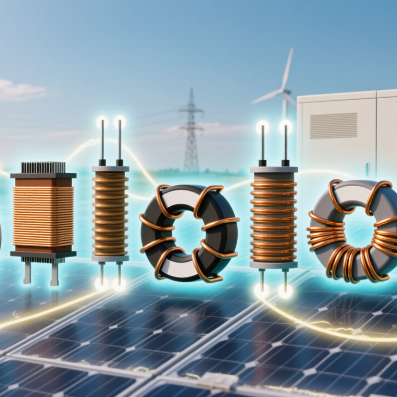
Solar Inverter Inductors: Functions, Types, and Essential Requirements
Solar inverter inductors store energy in magnetic fields and smooth current as power moves between photovoltaic panels, batteries, and the grid. They help limit ripple, reduce electromagnetic interference, and support stable conversion. Inside an inverter, a copper winding around a magnetic core may carry substantial current while heating gradually. That warmth is normal, but excessive temperature can shorten insulation life and alter performance.
Common options include ferrite-core inductors for high-frequency switching, powdered-iron designs for distributed air gaps, and laminated or amorphous-core parts in applications where lower-frequency losses matter. The right choice depends on switching frequency, current, voltage, and available space. Look for adequate saturation current, low winding resistance, suitable insulation, and a thermal rating that fits the enclosure. Core losses matter, too. They can be easy to underestimate.
A practical review checks temperature rise under realistic load, not just a datasheet value. Engineers should also consider vibration, humidity, and years of thermal cycling. A compact inductor may save space but run hotter; a larger one may ease cooling while adding weight and cost. There is no perfect trade-off. Testing the assembled inverter helps reveal what calculations miss.
Seven Top Inverter Inductor Options for Different Solar Applications
Solar inverters need inductors matched to switching frequency, current ripple, and cooling limits. The IEA PVPS report Trends in Photovoltaic Applications 2024 puts global installed solar capacity above 1.6 terawatts at the end of 2023. That scale makes component selection more than a bench-level detail. For compact string inverters, a gapped ferrite core offers low core loss at high frequency. Powdered iron suits designs needing gradual saturation, though it can run warmer. Sendust and amorphous cores are alternatives when designers balance loss, size, and cost. There is no universal winner.
Seven useful options serve different layouts: gapped ferrite for high-frequency conversion; powdered iron for ripple-heavy service; sendust for moderate loss and stable inductance; amorphous metal for efficient power stages; nanocrystalline material for high permeability; coupled inductors for interleaved converters; and planar inductors for low-profile assemblies. Small details matter. A rooftop inverter exposed to hot enclosure air needs thermal margin, not just a high current rating. In a three-phase unit, coupled windings may reduce ripple, but layout and control still matter. NREL’s inverter reliability research emphasizes that thermal stress and operating conditions affect service life; an inductor datasheet alone cannot predict field performance. Check saturation current, winding temperature, acoustic noise, and measured losses under the actual switching waveform. One caveat: published comparisons often use different test conditions, so rankings can mislead.
What Are the 7 Best Inverter Inductors for Solar Systems? - Seven Top Inverter Inductor Options for Different Solar Applications
How to Compare Inductance, Current Capacity, Core Materials, and Losses
What Are the 7 Best Inverter Inductors for Solar Systems?
The best choice depends on inductance, current capacity, core material, and losses. IEA PVPS reported about 407 GW of new solar capacity in 2023, increasing pressure on inverter efficiency and thermal reliability. For most designs, compare seven practical options: gapped ferrite, powdered iron, sendust, nanocrystalline, amorphous, laminated steel, and coupled inductors.
Measure inductance under operating current, not only at zero bias. A ferrite core can provide low loss at high switching frequency, but saturation may arrive suddenly. Powdered materials tolerate DC bias better, although their core losses can rise noticeably. Nanocrystalline and amorphous cores often support high current density, but their costs and winding complexity deserve scrutiny. Coupled inductors can reduce ripple and component count, yet poor coupling creates extra leakage loss.
Current capacity should include RMS heating, peak ripple, saturation margin, and ambient temperature. A 25°C rating can mislead inside a sealed inverter cabinet. Check copper loss, core loss, acoustic noise, and thermal resistance together.
IRENA’s Renewable Power Generation Costs in 2023 reported utility-scale solar PV at about 4.4 cents per kilowatt-hour, with costs falling roughly 90% since 2010. Small magnetic losses therefore deserve attention across long operating hours. I would not select the largest core automatically. Oversizing may reduce temperature, but it can increase weight, cost, and winding length. The datasheet may still hide real bias behavior.
Selecting Inductors for Residential, Commercial, and Utility-Scale Systems
What Are the 7 Best Inverter Inductors for Solar Systems?
Selecting Inductors for Residential, Commercial, and Utility-Scale Systems
Residential inverters usually benefit from compact ferrite-core inductors. They provide low losses at high switching frequencies and fit inside limited enclosures. Nanocrystalline inductors are another strong choice when current ripple and electromagnetic noise must remain low. For small rooftop systems, select a component with suitable saturation current, thermal rating, and insulation class. A quiet 5 kW inverter still needs careful heat management.
Commercial systems often require larger gapped ferrite, iron powder, or amorphous-core inductors. Gapped ferrite handles energy storage efficiently, while iron powder can tolerate changing loads with predictable performance. Amorphous cores may reduce core losses in demanding duty cycles. Compare copper temperature, airflow, vibration, and harmonic limits. Field testing often exposes problems that catalog values miss. A warm cabinet matters.
Utility-scale inverters call for laminated silicon-steel, nanocrystalline, or custom air-gap inductors. These designs manage high current, continuous operation, and substantial fault energy. Air-core inductors can avoid core saturation, but they need more physical space and careful magnetic-field control. The best seven choices depend on system voltage, switching frequency, ripple current, cooling method, and grid-code requirements. Do not select by inductance alone. Measurement matters. Engineers should verify impedance across frequency, acoustic noise, insulation distance, and temperature rise under real loading. A spreadsheet can miss a loose connection, uneven winding, or unexpected resonance. That is where the design may need revision.
Installation, Cooling, Testing, and Maintenance Requirements for Inductors
During installation, mount inverter inductors firmly and keep their airflow paths open. Leave clearance around the core and windings, following the equipment maker’s thermal limits. A cramped enclosure can trap heat near insulation and nearby components. Use short, secure connections, and check that terminals cannot loosen under vibration. Keep inductors away from water, conductive dust, and strong external magnetic fields. Small details matter.
Cooling should match the expected current, switching frequency, and ambient temperature. Do not assume a fan alone solves overheating; blocked filters and recirculated hot air can defeat it. The NREL 2024 Annual Technology Baseline uses a 15-year inverter replacement assumption in its utility-scale PV modeling. That is a planning assumption, not a guaranteed service life, but it supports regular condition checks. During commissioning, record winding resistance, insulation resistance, inductance, and operating temperature as baseline values. Compare later readings under similar load and temperature conditions. Unexplained drift deserves investigation.
Inspect for discoloration, cracked insulation, loose hardware, unusual hum, and dust buildup. Use qualified personnel and appropriate isolation procedures before testing; energized measurements can be hazardous. Thermography under meaningful load can reveal hot spots that a visual check misses. Clean cooling passages gently, and avoid solvents unless approved for the insulation system. Keep dated maintenance records. A slight rise in temperature may be normal; still, I would not dismiss a repeated change just because the inverter continues running.
 North American Safety Valve Industries, Inc.