Why Is a Pressure Safety Valve Important?

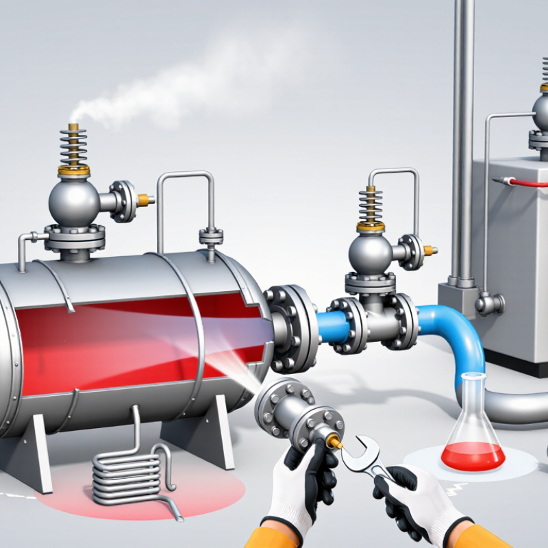
A Pressure Safety Valve is a small component with a critical responsibility. It protects vessels, pipelines, boilers, and process equipment from dangerous overpressure. When internal pressure rises beyond a set limit, the valve opens and releases enough pressure to reduce the risk of rupture. That response may take only seconds, but its reliability depends on careful design, installation, and maintenance.

In industrial environments, pressure can increase because of blocked outlets, excessive heating, chemical reactions, or control-system failure. A properly selected valve provides an independent layer of protection when ordinary controls are not enough. Engineers consider set pressure, operating temperature, discharge capacity, materials, and fluid characteristics. They also review manufacturer instructions and applicable engineering codes. The details matter. A valve installed backward cannot protect equipment correctly.

Inspection records, functional testing, and calibration help confirm that the valve remains ready. Dirt, corrosion, vibration, or an unsuitable discharge line can affect performance. Field technicians often examine the valve body, seals, springs, and connection points for warning signs. A leaking valve may indicate wear, incorrect settings, or changing process conditions. It should not be ignored.

Still, no Pressure Safety Valve can correct every design weakness. It cannot replace sound engineering, alarms, operator training, or an emergency plan. That limitation deserves honest attention. In practice, maintenance schedules may be delayed, and operating conditions may change without a full review. Reliable protection requires people to question those gaps. Understanding why this valve matters helps organizations protect equipment, workers, and surrounding communities with greater confidence.
Why Is a Pressure Safety Valve Important?

Define Pressure Safety Valves: Set Pressure Must Not Exceed MAWP

Why Is a Pressure Safety Valve Important?

A pressure safety valve (PSV) protects equipment when internal pressure rises beyond a safe limit. It opens automatically and releases excess pressure before a vessel, pipeline, or boiler suffers serious damage. The key control is set pressure. This is the pressure at which the valve begins to open. It must not exceed the equipment’s maximum allowable working pressure (MAWP). If the PSV is set higher than the MAWP, the protected equipment may already be overstressed before relief begins. That is a dangerous design error.

MAWP is determined by the vessel’s materials, thickness, temperature, and construction details. A qualified engineer should confirm it from approved drawings, calculations, and nameplate data. In real maintenance work, small errors matter: a damaged tag, an outdated data sheet, or an incorrect spring setting can change the protection level. The valve must also be correctly sized for the possible pressure source and installed where pressure can reach it freely. It sounds simple. It is not always simple.

Tips: Record the MAWP beside the PSV set pressure. Check both during every inspection. Keep inlet and outlet paths clear. Verify calibration with controlled testing and competent personnel. Never adjust the setting casually in the field. I have seen assumptions survive longer than equipment records, and that is worth questioning. A careful review may reveal a mismatch before the system is pressurized.
Identify Overpressure Causes: Process Upsets, Blocked Outlets, and Fire Exposure

Why Is a Pressure Safety Valve Important?

A pressure safety valve protects equipment when pressure rises beyond a safe limit. It is the final barrier, not a routine control device. Process upsets can create sudden pressure increases. A runaway reaction, failed cooling system, or malfunctioning control valve may generate heat and vapor rapidly. Even a brief upset can challenge a vessel designed for much lower pressure.

Blocked outlets create another serious hazard. A closed isolation valve, clogged filter, frozen line, or solid buildup can trap fluid inside equipment. Thermal expansion can then raise pressure quietly. The danger may remain invisible until a gauge shows an alarming reading. Small details matter here.

Fire exposure is different but equally severe. External flames heat a vessel, causing its contents to boil and produce expanding vapor. The pressure safety valve must release enough flow before the metal loses strength. Engineers therefore check set pressure, relieving capacity, backpressure, discharge routing, and material suitability. Inspection records and functional testing also matter. A valve can be correctly selected yet poorly maintained.

The uncomfortable lesson is that the valve is not a magic shield. Poor sizing, blocked discharge piping, or an isolated valve can defeat its purpose. Operators need clear procedures and practical training. Sometimes the overlooked warning is the most important one.

Apply ASME VIII Limits: 10% Accumulation for Most Pressure-Vessel Cases

Why Is a Pressure Safety Valve Important?

Apply ASME VIII Limits: 10% Accumulation for Most Pressure-Vessel Cases

A pressure safety valve protects a vessel when pressure rises beyond its designed operating range. The risk may begin quietly. A blocked outlet, failed control valve, or heated liquid can increase pressure rapidly. Without reliable relief, vessel walls, welds, and connected piping may face severe stress.

ASME Section VIII commonly permits 10% accumulation for most pressure-vessel applications. Accumulation means the pressure rise above the vessel’s maximum allowable working pressure during relieving. For example, a vessel with a 100 psig MAWP may reach 110 psig under the applicable relieving condition. The valve’s set pressure and the permitted accumulation are related, but they are not identical. That distinction is often missed.

The 10% limit is not a universal shortcut. Multiple-valve arrangements, fire exposure, and special service conditions may use different limits. Engineers should verify the exact ASME edition, vessel category, relieving scenario, and local requirements. Capacity calculations must also consider back pressure, temperature, fluid phase, and discharge piping. A valve can be correctly sized on paper yet perform poorly with an undersized outlet.

Small details matter. Check the nameplate, set pressure, test records, and isolation-valve position. Review them together. A realistic design review should question its own assumptions, especially when process conditions change. Even a clean calculation can fail if field installation differs.

Why Is a Pressure Safety Valve Important?

ASME Section VIII generally limits accumulation to 10% above the vessel’s maximum allowable working pressure for most single-pressure-relief-device cases.

This illustration uses a vessel with a maximum allowable working pressure (MAWP) of 1.00 MPa. The pressure safety valve is set at 1.00 MPa, while the maximum permitted relieving pressure for the typical 10% accumulation case is 1.10 MPa. The valve helps prevent pressure from exceeding the code-based safety limit.

Evaluate Fire Scenarios: API 521 Allows Up to 21% Accumulation

A pressure safety valve protects equipment when pressure rises beyond a safe operating range. In a fire, external heat can vaporize liquid inside a vessel rapidly. Pressure may increase even after normal controls stop responding. The valve provides a controlled discharge path.

For fire exposure, API 521 guidance allows up to 21% accumulation in certain relief design cases. This allowance is not a universal target. Engineers must confirm the applicable pressure vessel code, system limits, and project requirements. The relieving pressure must remain compatible with the vessel’s maximum allowable working pressure. A small calculation error can become a serious weakness.

The evaluation begins with the vessel’s wetted surface area, fluid properties, fire heat input, and expected vapor generation. Engineers also check whether insulation, drainage, or fire protection changes the heat load. The valve must pass enough flow at the calculated relieving conditions. Its inlet piping should avoid excessive pressure loss, while the outlet should discharge safely.

Field experience shows that neglected details often matter. A blocked outlet, incorrect set pressure, or undersized drain can distort the analysis. Testing records also deserve careful review. They may look complete but still miss actual operating conditions. I would not treat 21% as extra operating room. It is a controlled design allowance, requiring documented assumptions and independent review. Some cases remain uncertain, especially when fire duration or fluid behavior is poorly defined.

Size and Maintain PSVs: Follow API 520 Capacity and Inspection Requirements

Why Is a Pressure Safety Valve Important?

Pressure safety valves protect vessels when pressure rises beyond a safe operating limit. Correct sizing is not guesswork. API 520 Part I requires engineers to calculate relieving capacity from the fluid, temperature, pressure, and discharge conditions. For many single-valve applications, design codes commonly limit overpressure to 10 percent. That figure is not universal. The governing code and process scenario still control.

Small errors matter. A blocked outlet, fire exposure, or unexpected phase change can create a very different relieving load. API 520 calculations cover gas, steam, liquid, and two-phase services, but each case needs suitable assumptions. A spreadsheet may look correct while using the wrong molecular weight or fluid phase. That happens. Independent review can catch it.

Maintenance must follow service risk, not habit. API 576 recommends inspection planning based on operating history, service conditions, valve performance, and previous findings. Inspectors should check inlet restriction, outlet backpressure, corrosion, deposits, leakage, and set-pressure verification. API 520 Part II also addresses installation details, including discharge piping and reaction forces. Records should show the set pressure, test date, capacity basis, findings, and corrective action. A valve that passed years ago may not protect today’s process. That uncomfortable point deserves more attention.

Why Is a Pressure Safety Valve Important? — Size and Maintain PSVs: Follow API 520 Capacity and Inspection Requirements

Data Dimension Practical Requirement or Fact Why It Matters Applicable Reference
Primary safety function A pressure safety valve (PSV) opens at a defined set pressure to relieve excess pressure and closes after the relieving condition is controlled. It helps protect pressure-containing equipment from overpressure, reducing the risk of rupture and hazardous release. API 520 Part I; ASME Section VIII, Division 1
Sizing basis Determine the governing overpressure scenario, required relieving rate, fluid properties, relieving temperature, relieving pressure, back pressure, and allowable accumulation before selecting the effective discharge area. The worst credible scenario—not normal operating flow—normally controls the required valve capacity. API 520 Part I
Common overpressure scenarios Blocked outlet, external fire exposure, control-valve failure, thermal expansion of blocked-in liquid, utility failure, tube rupture, and abnormal process reaction. Each scenario can produce a different required relieving load and may require separate evaluation. API 521; API 520 Part I
Set pressure Set pressure is the pressure at which the valve is adjusted to open. It must be coordinated with the protected equipment’s allowable pressure and the governing design code. An unsuitable set pressure can cause premature opening or fail to provide adequate overpressure protection. API 520 Part I; ASME Section VIII
Accumulation and overpressure The permitted pressure increase above the set pressure depends on the applicable construction code, service, and relief scenario. Do not assume one universal percentage for every installation. Relief-capacity calculations are valid only when the allowed accumulation and relieving conditions are correctly established. ASME Section VIII; API 520 Part I
Gas or vapor capacity For compressible fluids, capacity calculations use relieving pressure and temperature, molecular weight, compressibility, isentropic exponent, and the applicable certified coefficient of discharge. Small changes in gas properties or relieving conditions can materially change the required area. API 520 Part I
Liquid capacity For liquids, sizing considers required mass flow, liquid density at relieving conditions, viscosity, pressure differential, and the valve’s certified liquid-capacity coefficient. Liquid relief sizing differs from gas sizing and must account for viscous and potentially flashing service. API 520 Part I
Two-phase or flashing service A qualified two-phase relief method is required when liquid and vapor may discharge together or when flashing occurs during depressurization. Using a single-phase equation for two-phase flow can significantly understate the required capacity. API 520 Part I; API 521
Back pressure Evaluate superimposed and built-up back pressure, including discharge-system pressure losses and changes during relief. Back pressure can affect opening behavior, stability, capacity, and reseating performance. API 520 Part I and Part II
Inlet installation Keep inlet pressure loss within the limits established by the design basis and applicable standards; minimize restrictions and avoid arrangements that can cause instability. Excessive inlet loss may cause chatter, reduced capacity, or unreliable operation. API 520 Part II
Discharge piping Design the outlet system for reaction forces, pressure loss, drainage, thermal effects, corrosion, safe discharge location, and possible two-phase flow. A correctly sized PSV can still perform poorly if the discharge system creates excessive or unstable back pressure. API 520 Part II; API 521
Valve selection Select conventional, balanced-bellows, pilot-operated, or other suitable construction according to back pressure, fluid compatibility, temperature, fouling potential, and required stability. Valve type affects operating reliability, maintenance needs, and resistance to back-pressure effects. API 520 Part I
Material compatibility Confirm that body, trim, spring, bellows, seals, and wetted materials are suitable for the process fluid, concentration, temperature, corrosion mechanism, and environmental conditions. Corrosion, erosion, plugging, or seal degradation can prevent the valve from opening or reseating correctly. API 520 Part I; API 576
Inspection program Establish inspection, testing, repair, and replacement procedures based on service severity, failure history, operating experience, regulatory requirements, and risk. API guidance supports a risk-informed program; it does not create one universal inspection interval for every PSV. API 576
Typical inspection activities Review records, verify identification and set pressure, inspect inlet and outlet piping, check for leakage or corrosion, examine parts, and perform a suitable bench test or in-service test where permitted. Inspection confirms that the installed valve remains identifiable, available, mechanically sound, and capable of performing its protective function. API 576
Bench testing Use calibrated equipment and documented procedures to verify opening behavior, set pressure, reseating, and leakage performance as applicable to the valve design and service. Testing provides evidence that the valve meets its specified functional requirements after service or repair. API 576; API 527
Seat tightness Apply the relevant seat-tightness acceptance method and test pressure for the valve type and service; acceptance criteria must be defined before testing. Uncontrolled seat leakage can create emissions, product loss, corrosion, or unsafe operating conditions. API 527
Documentation Retain the valve tag, service, set pressure, relieving case, certified capacity, materials, test results, repair history, and next planned inspection date. Complete records support traceability, future sizing reviews, audit readiness, and safe maintenance planning. API 520; API 576
Change management Reassess PSV sizing and suitability after changes to process composition, throughput, equipment design pressure, operating temperature, relief scenarios, or discharge piping. A valve that was adequate for the original design may no longer protect the modified system. API 520 Part I; API 521; API 576

Note: API 520 primarily addresses pressure-relief device sizing, selection, and installation. Inspection and maintenance practices are addressed principally by API 576, while seat-tightness testing is covered by API 527. Always apply the governing jurisdictional and equipment design-code requirements.